FPC Design Notes: Bend Areas, Stiffeners, and the Checks That Prevent Rework
Most FPC prototype rework comes from four places: bend areas, stiffeners, line width and spacing, and coverlay openings. Work through the 10-point checklist before you build.
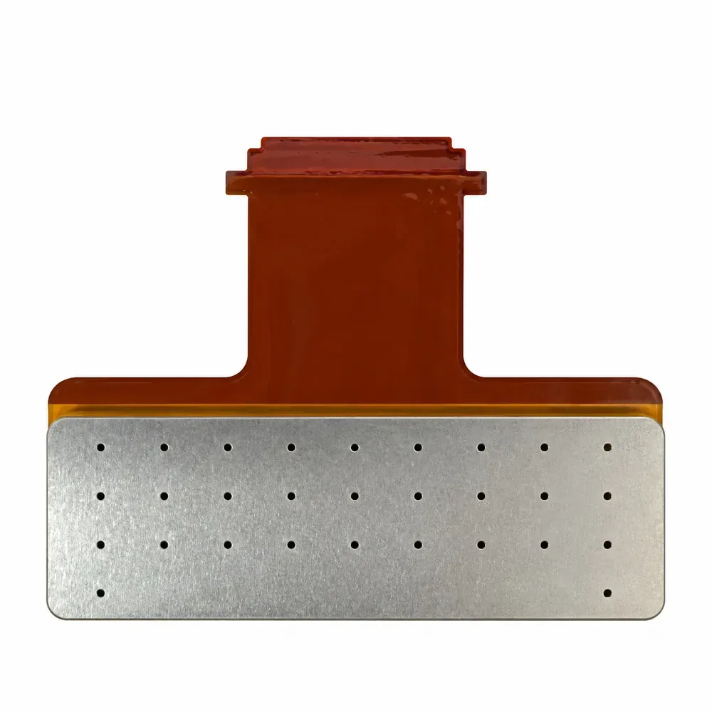
Short answer: most FPC prototype rework comes from four places — the bend area, the stiffener, the line width and spacing, and the coverlay openings (windows). Keep the bend radius matched to how many times the board bends, route the traces along the bend line, and keep openings and vias out of the bend area. Then work through the 10-point checklist at the end before you build.
The bend area
A flex circuit fails in the bend area first, so design it first. Allow a bend radius that matches the number of bends the board will see over its life, and keep the radius generous where the board folds again and again. Route the traces along the bend line, not across it, so the copper bends instead of stretching. Do not put coverlay openings or vias in the bend area — both concentrate stress where the board is already working hardest.
Stiffeners
Stiffeners are there to hold a part of the board still: under a connector, under components, or where the board is fixed in place. Choose the material for the job — polyimide for a thin, light stiffener, a steel plate where the area must stay flat and rigid, or FR4 where the board needs a thicker, board-like support. Check the stiffener position and its bonding tolerance against the assembly it has to fit.
Line width and spacing
Leave margin in the line width and spacing. Designing exactly at the minimum leaves no room for etching variation, and a tight trace next to a tight gap is where shorts and opens start. Where a trace carries current or runs close to a neighbour, give it more room than the minimum.
Coverlay openings and solder mask
The coverlay window has to land on the pad it is meant to expose, and stay clear of the traces around it. An opening that drifts onto a trace, or one that is too small for the pad, causes the same failures at assembly that a bad board does. Check the opening-to-trace clearance and the mask opening against the pad size before the design goes out.
Pre-prototype checklist
Run through these ten checks before you send a design for prototyping: 1. The bend areas are defined and the bend radius matches the number of bends. 2. Traces run along the bend line, not across it. 3. No coverlay openings and no vias sit in a bend area. 4. Stiffeners are placed where parts are mounted or the board is fixed. 5. Stiffener material matches the job — polyimide, steel or FR4. 6. Line width and spacing leave margin above the minimum. 7. Coverlay openings line up with their pads. 8. Openings stay clear of nearby traces. 9. The stack-up and materials are the same on every page of the drawing. 10. The Gerber files and the drawing agree with each other.
The three most common causes of rework
The first is a bend area that was designed like a rigid board — traces across the bend, a window in the fold, or a via in the bend. The second is a stiffener that is in the wrong place or made from the wrong material, so the board flexes where it should stay still. The third is line width and spacing set at the minimum, with no margin for the process. Fix those three, and most prototype rounds come back clean.